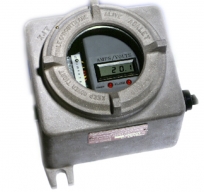
VCM-EE in Explosion-Proof Enclosure
- Overview
- Key Benefits
- Specifications
MPS’ most popular model in a protected explosion-proof enclosure. Applicable for Explosion-Proof Environments.
For the most complete protection on large, or critical machines, the VCM-E is ideal due to its higher shaft current measurement capacity, uninterrupted grounding, continuous monitoring via 4-20mA signals and alarms for alerting operators to dangerous conditions such as grounding device failure or increase in shaft voltage. VCM-E’s continuously monitor shaft voltage and/or grounding/earthing current providing three 4‑20 mA output signals (per VCM-E) for remote monitoring and trending.
- Explosion Proof
- Prevent Shaft Current Damage
- Shaft Current Sparking Confined or Controlled
- Train Performance Tracking, Aiding Operation
- Continuous Train Performance Sensing and Tracking
- Continuous Train Trending Aiding in Maintenance Scheduling
- Alarms when shaft grounding devices have lost contact with the shaft.
- Alarms on high and low grounding current and/or high shaft voltage.
| TEMPERATURE: | ||
| Operating Range: | -10°C to 50°C (14°F to 122°F) | |
| Relative Humidity: | 0% to 95%, non-condensing | |
| Storage Range: | -23°C to 60°C (-10°F to 140°F) | |
| POWER REQUIREMENTS: | 100-240 Vac, 50/60Hz input into the MPS supplied power supply. | |
| INPUT: | ||
| Current:100mV | (use shunt with 100mV/ full scale rating) | |
| (Max. input voltage equals +/-10V) | ||
| Voltage: | +/- 1V (Max. input voltage equals +/-5V) | |
| +/- 10V (Max. input voltage equals +/-50V) | ||
| +/- 100V(Max. input voltage equals +/-300V) | ||
| Frequency Response: | 30 Hz to 10 KHz | |
| OUTPUTS: | ||
| Monitoring: | ||
| Local: | 3½ digit LCD display, indicating Average Current, Peak Current, Peak Voltage, and Power/Alarm Check, selectable with rotary switch. | |
| Remote: | 4 to 20 mA (Load impedance not to exceed 500 ohm) signal representative of Peak Current.* | |
| 4 to 20 mA (Load impedance not to exceed 500 ohm) signal representative of Average Current.* | ||
| 4 to 20 mA (Load impedance not to exceed 500 ohm) signal representative of Peak Shaft Voltage.* | ||
| Optional latching available. | ||
| Alarms: | ||
| Local: | LED’s for high and low current and high voltage.* | |
| Remote: | Unified, single relay opening (10 watts, 0.5 A, and 100 Vdc) (100Ω minimum load) for high & low current and high voltage.* | |
| NOTE: Maximum shaft current is equal to shunt rating. Maximum shaft voltage is 1, 10, or 100 V (selectable). | ||
| DIMENSIONS: | ||
| Length: | 7.6 inches (193 mm) | |
| Width: | 7.8 inches (198 mm) | |
| Height: | 7.6 inches (193 mm) | |
| Weight: | 15.0 pounds (6.8 kg) | |
| * For shaft current monitoring and alarm, a 100 mV current shunt for 1, 2, 5, 10, 20, 50, or 100 A is required. | ||
| For shaft voltage monitoring and alarm, a shaft voltage sensing device is required. | ||
| RATINGS: | Class I Groups C & D and Class II Groups E,F,G. | |
| CENELEC EExd IIB+H2 T6 | ||
| Order Code: | VCM-EE | |